6. CONFIGURATION MAINTENANCE
6.1 Devices
On the device management page, you can add devices (such as IPC, DVR, NVR) through automatic search, manual addition, or batch import. The platform supports the following device types:
- IPC;
- DVR;
- NVR;
- Thermal Camera;
- Facial Capture Camera;
In the main menu, click on "Devices" to access the detailed page, as shown in Figure 6-1.
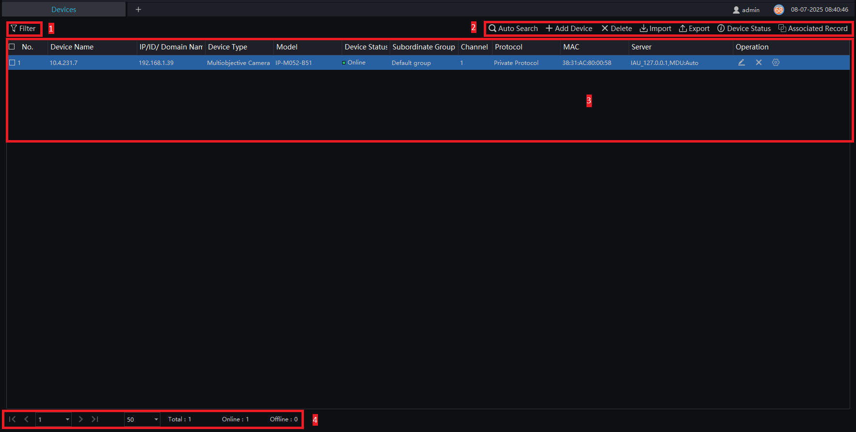
Key Features and Functions:
| Number | Function | Description |
|---|---|---|
| 1 | Filter | Filter devices by setting the device type, online status, and device name. |
| 2 | Operation | Search, add, delete, export, import devices; view the status of all devices; associated recordings (if both the camera and the NVR are connected to the platform, recordings from the NVR can be synchronized with the IP cameras). |
| 3 | Device Information Display | View device details; operational options: edit, delete device, or quickly access the device configuration. |
| 4 | Page | Displays device pages, the next page, and the total quantity. |
6.1.1 Auto Search
The device and the server must be on the same network segment.
Procedure:
Step 1: On the device management page, click on "Auto Search" to access the detailed page, as shown in Figure 6-2.
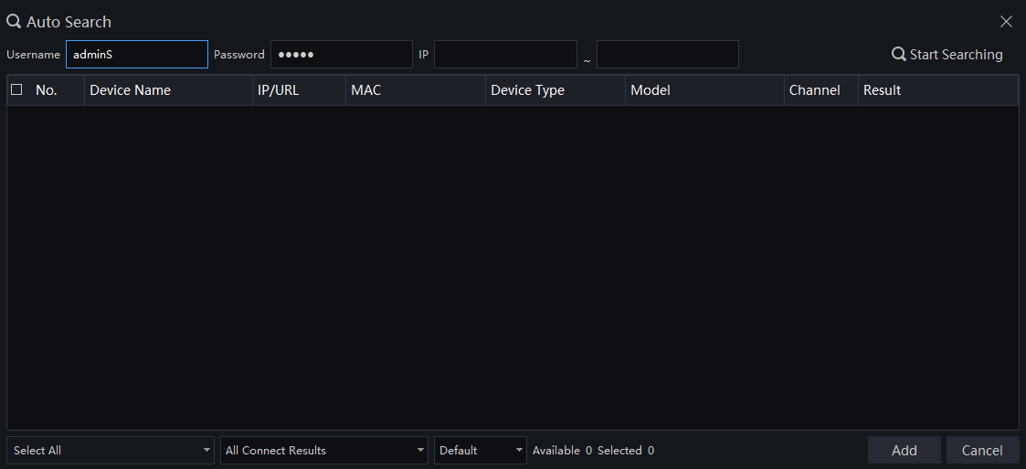
Step 2: Enter the device's username and password, and set the IP range filter.
Step 3: Click on "Start Searching". The device on the same network as the client will be automatically searched, and the results will appear on the current page.
Step 4: Select the desired devices and click on "Add." Once completed, the device will be displayed in the device list.
All devices can be added to the list, but if any device fails to connect, the reason might be an incorrect password or a configuration error. Modify the device settings manually to resolve the issue.
6.1.2 Add Manually
Procedure:
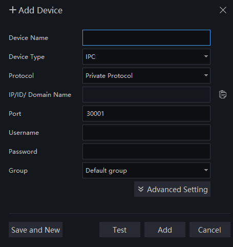
Step 1: Click on "Add Device" on the devices page, as shown in Figure 6-3.
The intelligent analysis server does not support automatic addition; it only supports cameras with facial detection.

For advanced settings, the default connection mode is "Add from Platform" If you want to switch to the "Registration" mode, configure the parameters in the device's web interface (Configuration > Network Service > Platform Access) using advanced settings.
Step 2: Enter the device name, select the device type, input the IP address/username/password, and select the group.
Step 3: Click on "Test" to verify the settings, then click on "Save and New."
Step 4: A pop-up window appears "Added successfully," and the device will appear on the device management page (the device details will also appear on the page simultaneously).
Step 5: To delete cameras, select the number of cameras, click on "Delete," and then confirm by clicking "OK" to remove the cameras.
6.1.3 Export or Import Device
Procedure:
Step 1: Click on "Export."
Step 2: Click on "Export Template," and edit the information on the template page.
Step 3: Click on "Import."
Step 4: Select the file to be imported and click Save.
6.1.4 Device Status
Procedure:
Step 1: Click on "Device Status."
Step 2: A pop-up window displays the status of the devices, as shown in Figure 6-5.
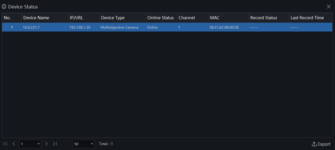
Step 3: Click on "Export."
Step 4: Set the folder where you want to save the file.
6.2 Device Config
In the "Device Config" interface, you can view and configure device parameters such as bitrate parameters, motion detection parameters, OSD parameters, image parameters, and maintenance for IPC. For NVR devices, users can configure recording strategies and disk management. For thermal cameras, users can configure thermal parameters, smoke and flame detection, etc.
The configuration functionality is related to the firmware version of the device.
In the main menu, click on "Configure Device" to access the detailed page, as shown in Figure 6-6.
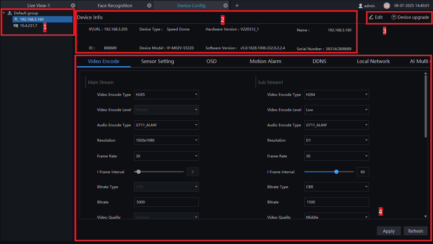
Key Features and Functions:
| Number | Function | Description |
|---|---|---|
| 1 | Organization Structure | Displays the organization structure information. |
| 2 | Basic Information | Displays the basic information. |
| 3 | Edit/Device Upgrade | Edit: Edit the device information. Device Upgrade: Click to upgrade the device immediately. |
| 4 | Device Configuration | Displays and allows the configuration of the device. Click "Apply" to save the information. |
6.3 Group
For large-scale surveillance, groups can be created to perform hierarchical management of devices. The system's default configuration includes a root group that supports up to 6 layers.
In the main menu, click on "Group" to access the detailed page, as shown in Figure 6-7.
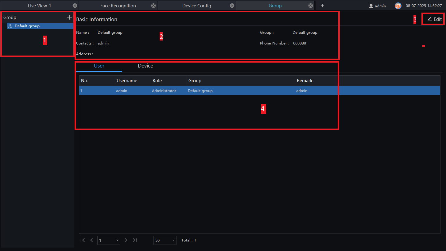
Key Features and Functions:
| Number | Function | Description |
|---|---|---|
| 1 | Group | Displays the group tree; new groups can be added by clicking on the "+" button. |
| 2 | Basic Information | Displays the basic information of the device or group. |
| 3 | Edit | Basic information can be edited by clicking on "Edit." |
| 4 | User or Device Display Area | Displays user or device information. |
6.3.1 Add a Group
Procedure:
Step 1: Click on "+" to add a new group, as shown in Figure 6-8.

Step 2: Enter the name, group, phone number, contacts, and address.
Step 3: Click on "Save and New" to save and create a new group simultaneously.
Step 4: Click on "Save" to save and finalize.
6.4 Log
In the "Log" interface, users can query the operation log, server log, and system log.
In the main menu, click on "Log" to access the detailed page, as shown in Figure 6-9.
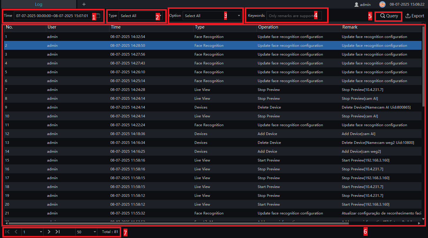
Key Features and Functions:
| Number | Function | Description |
|---|---|---|
| 1 | Time | Define the start and end time for the query. |
| 2 | Log Types | The default is to select all. |
| 3 | Log Option | The default is to select all. There are many options, allowing more detailed logs to be chosen separately. |
| 4 | Keywords | Define a keyword for quick queries. |
| 5 | Query | Executes the log search based on the previous settings. |
| 6 | Result | Displays the query results. |
| 7 | Interface Display | Shows the current page of logs, the number of logs, and the option to navigate to the next page. |
6.5 Users
On the user page, you can add users, modify user privileges, search, or delete users through the user management feature.
The system includes a default Administrator and Operator:
- Administrator: Has all privileges.
- Operator: Has partial privileges.
In the main menu, click on "Users" to access the detailed page, as shown in Figure 6-10.
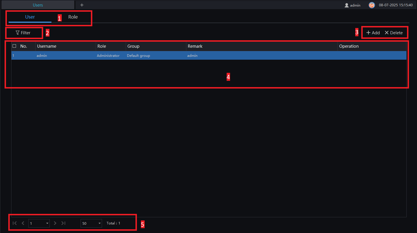
Key Features and Functions:
| Number | Function | Description |
|---|---|---|
| 1 | Users and Role | Choose users or roles to manage. |
| 2 | Filter | Set filter criteria; choose role, group, or user name for filtering. |
| 3 | Add/Delete | Add or delete a user or role. |
| 4 | Display Area | Displays user or role information. |
| 5 | Interface Display | Shows the current page of users/roles, the number of users, and an option to navigate to the next page. |
6.5.1 Add User
Procedure:
Step 1: In the user management interface, click "Add" to add a new user.
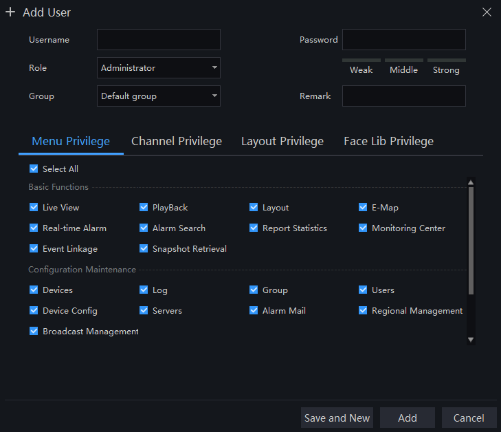
Step 2: Enter the name. Users can be set as "Administrator" or "Operator" by default.
Step 3: Set a password and assign the user to a group.
Step 4: Select the user's privileges.
Step 5: Click "Save and New" or "Add" to save and add the user. A pop-up window appears the message "Added successfully."
6.5.2 Add Role
Procedure:
Step 1: In the user management interface, click on "Role" to access the interface shown in Figure 6-12.
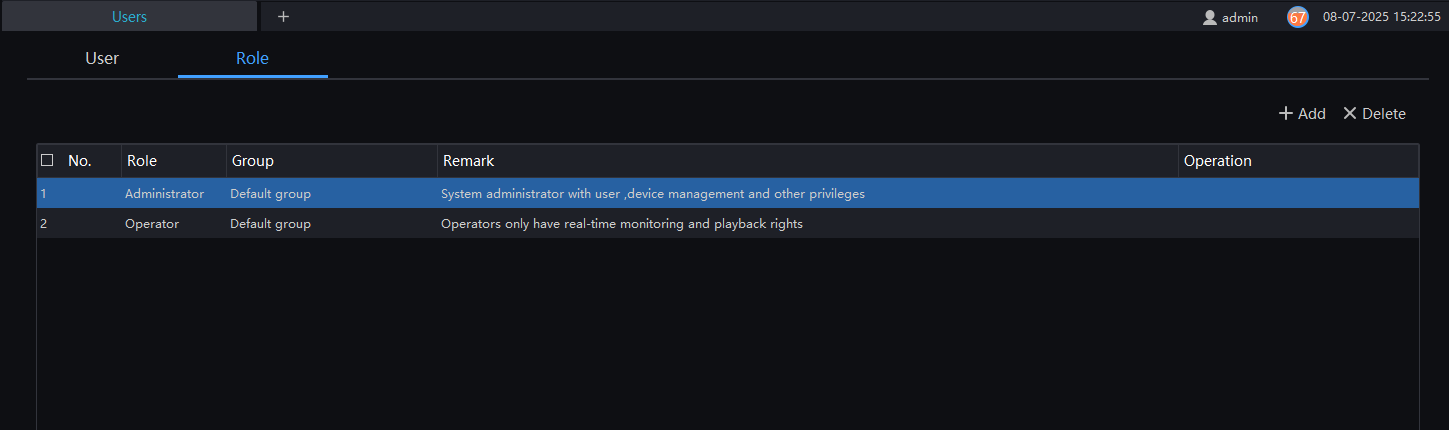
Step 2: Click on "Add," then enter the role name, group, and a description.
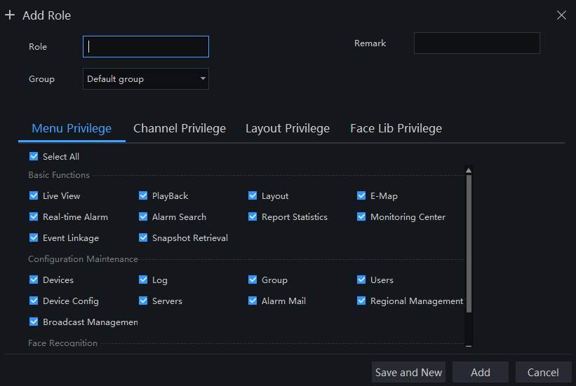
Step 3: Select the privileges for the role.
Step 4: Click on "Save and New" to save the current settings or "Add" to finalize the addition.
Step 5: The added role will be displayed in the interface. Click "Edit" or "Delete" to modify or remove the role.
6.6 Servers
In the server interface, you can view execution status, performance data, and server parameter configurations to better understand server runtime data and perform more efficient system maintenance.
In the main menu, click on "Servers" to access the detailed page, as shown in Figure 6-14.
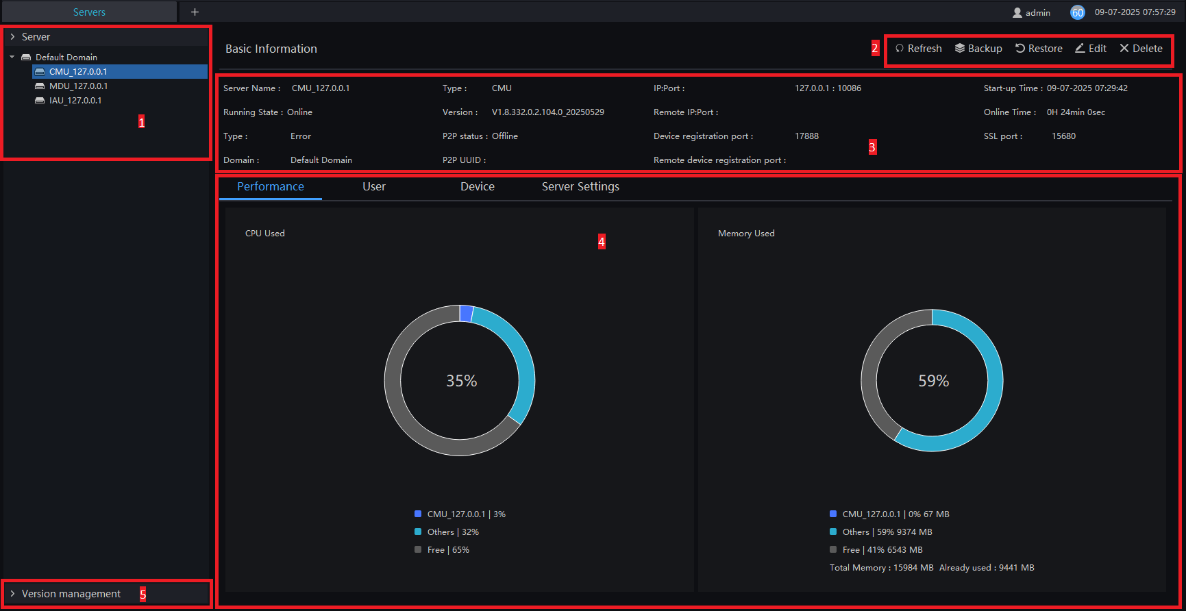
Key Features and Functions:
| Number | Function | Description |
|---|---|---|
| 1 | Servers | Default Server, CMU/MDU/IAU Server. |
| 2 | Basic Operations | Refresh page, backup, restore, edit, and delete. |
| 3 | Basic Information | Basic server details. |
| 4 | Server Performance | Displays the performance information of the selected server. |
| 5 | Version Management | Release versions to the server and update the version for connected clients. |
6.6.1 Central Management Server
Data backup and recovery are typically used for system migration. This process involves two main steps:
-
Data Backup:
- Involves downloading the data from the server where WCAM is installed.
- Backup data includes database information such as:
- Users
- Devices
- Servers
- Alarms
- Logs
- Face photos, among others.
-
Data Recovery:
- Involves uploading the backup data to the servers.
- This step includes performing recovery operations and ensuring the system returns to normal functionality.
In server settings, users can configure the general parameters for the face capture limit. These parameters can be applied to all cameras with these functions, as shown in Figure 6-15.
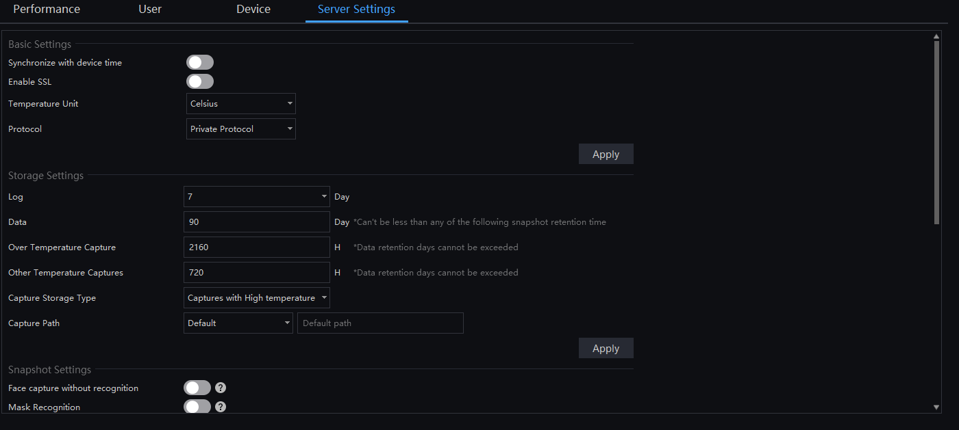
If the retention time for Over Temperature Capture is null, it means that the image capture time will match the data storage duration in days.
If the retention time for over-temperature/temperature capture is set to 0, it means that captured images will not be saved.
There are five server configurations:
-
Basic Settings: Time synchronization, enabling SSL, temperature unit, and device logging protocol.
-
Storage Configuration: Log retention days, data storage days, over-temperature capture retention time, other temperature capture retention time, Capture Storage Type, and capture path.
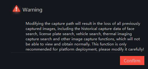
When the Capture Path is changed, the following message is displayed:
- Snapshot Settings: Face recognition, mask recognition, no-mask alarm, capture time, remove duplicate objects, and face algorithm mode.
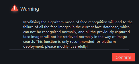
When the face algorithm mode is changed, the following message is displayed:
Enable Face capture without recognition, skip facial recognition operations, and perform only temperature measurement management. All captured faces will be treated as strangers and cannot be searched using the image search function. The Face capture without recognition mode is suitable for scenarios where identifying individuals is not a concern, such as airports, subways, stations, other access controls, parks, and public service agencies.
-
Face Capture Limit: Ambiguity, confidence coefficient, face size (length), and face size (width).
-
Alarm Configuration: Remove repeat alarm time period.
6.6.1.1 Data Backup
Procedure:
Step 1: Click on  in the top-right corner. A window will appear, as shown in Figure 6-16.

Step 2: Navigate to the backup path and click on "Start Backup" to back up the server data.
Step 3: Once the backup is successful, the backup progress will be displayed as "100%."
Step 4: Click on  to exit the backup process.
6.6.1.2 Restore Backup
Click on "Restore", and a window will appear, as shown in Figure 6-17.

6.6.2 Media Distribution Server
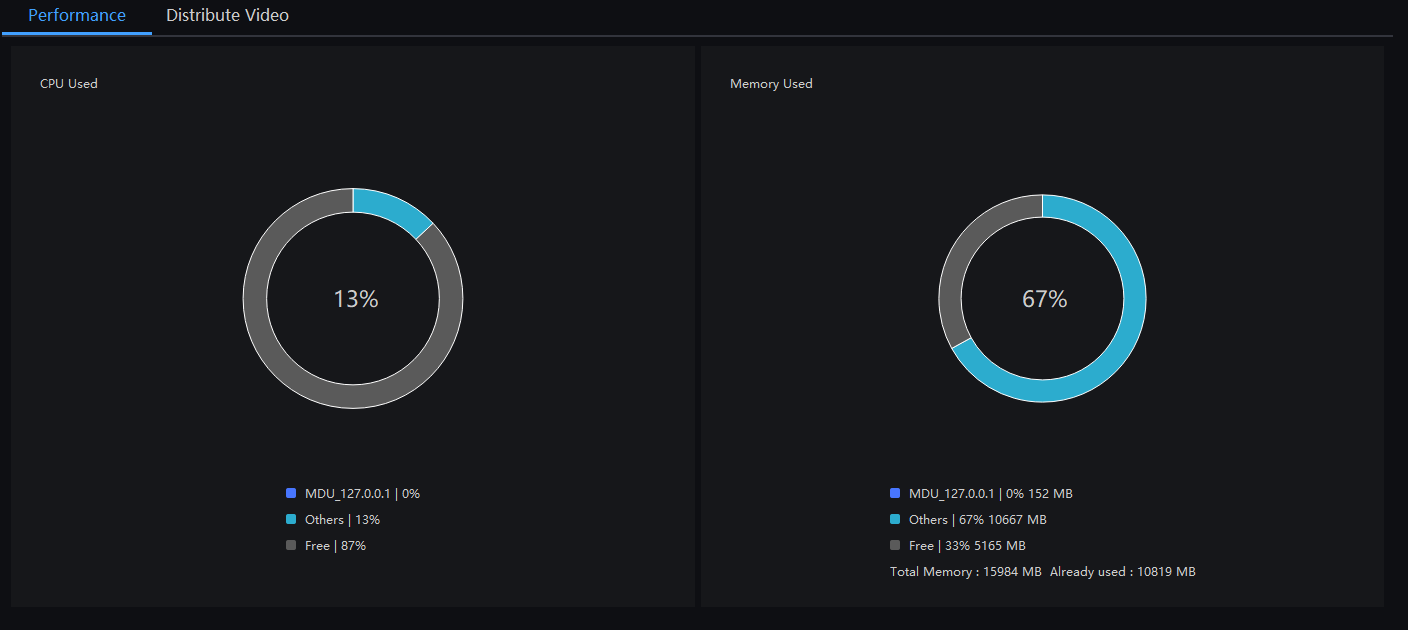
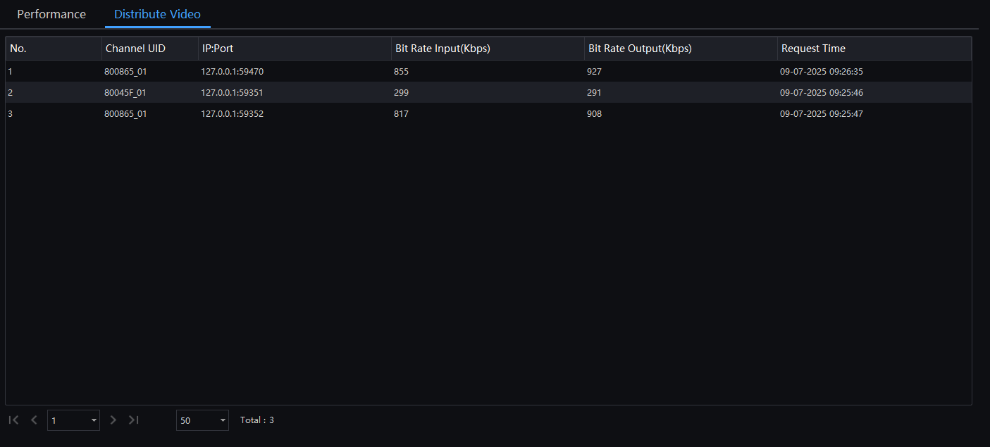
6.6.2.1 Performance and Status
6.6.3 Intelligent Analysis Server
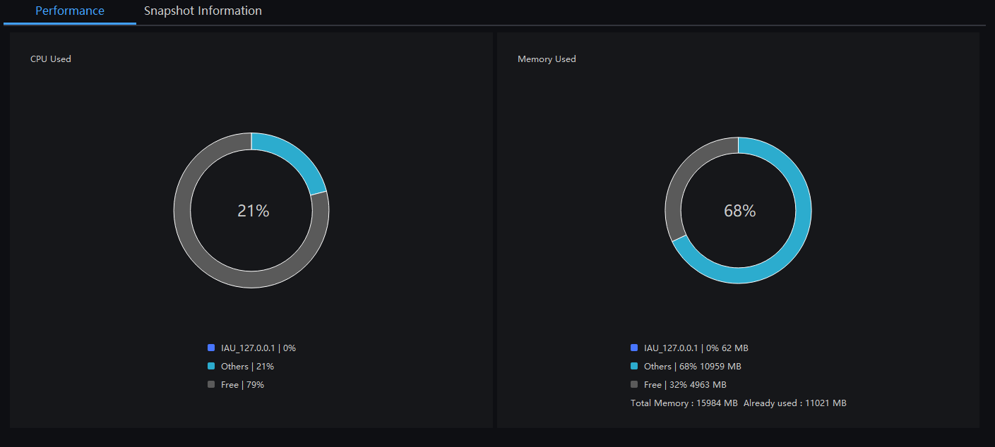
6.6.3.1 Performance and Capture Information
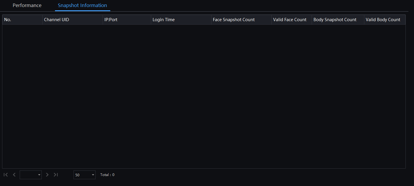
Snapshot Information is generally applicable to the facial capture device; it can analyze the image if the device captures correctly. If the number of captured faces is 0, check if the camera is configured properly.
6.6.4 Version Management
6.6.4.1 Version Management
Version management is used for the decentralized deployment of servers and client installations, facilitating the version update of all clients.
When the server uploads and updates the latest software version, all clients corresponding to the same server can receive notifications and manually perform the update.
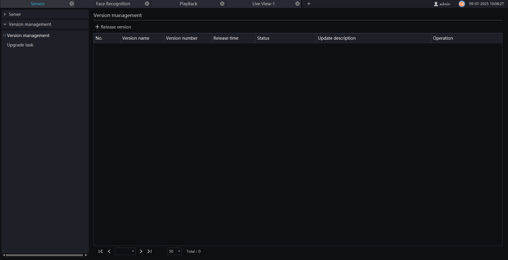
In the version management interface, click on "Release Version" to upload the latest version and install it on the server. All uploaded versions will be displayed in the list, and users can operate them.

6.6.4.2 Upgrade task
In the upgrade task interface, users can upload the version to the server. Click on "Update to the Latest Version" to perform the update. Clients on the same server can detect the version and will receive a reminder to update.
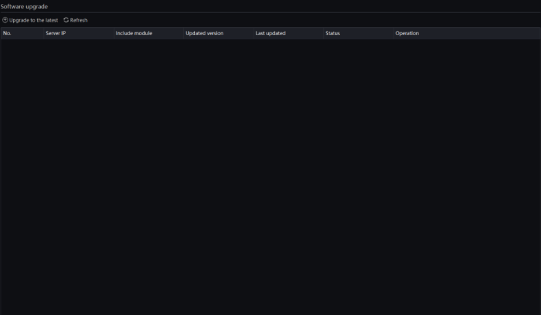
When opening the client, you will see the update reminder. Click on "Update" to proceed with the update.
6.7 Alarm Mail
Define the sender and recipient information for alerts. When an alert is sent, it can be forwarded to the corresponding people via email.
In the main menu, click on "Alarm Mail" to access the detailed page, as shown in Figure 6-25.
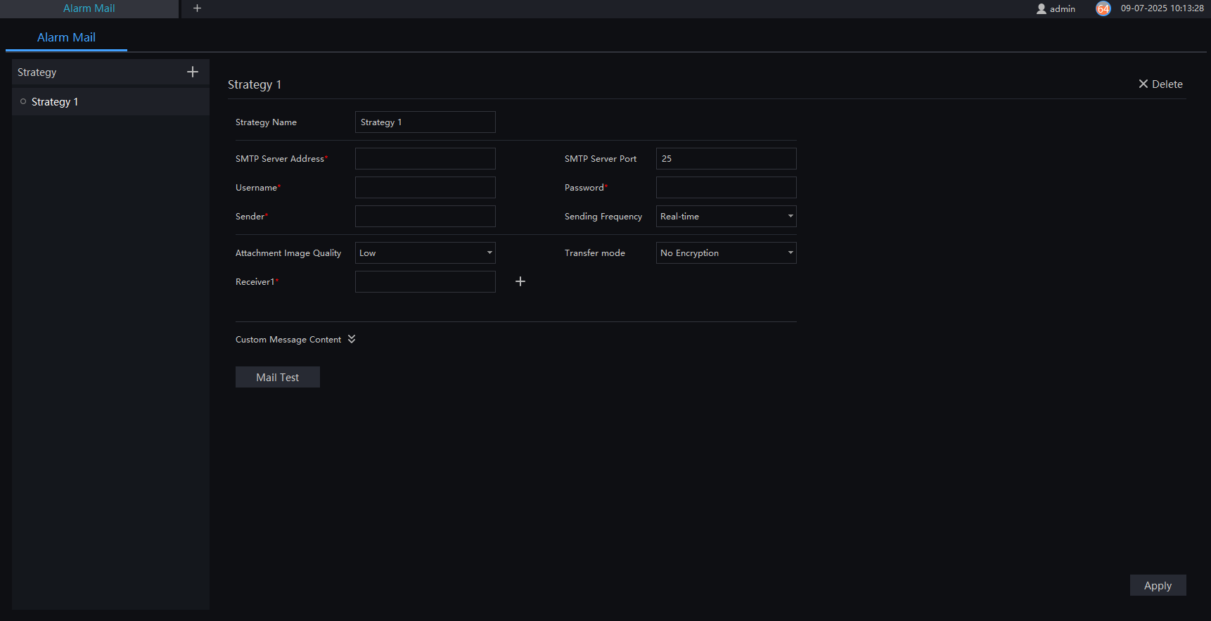
Procedure:
Step 1: Click on  to add a new strategy.
Step 2: Enter the name and the necessary information for using SMTP.
Step 3: The alarm can be sent via email with a personalized message.
Step 4: Click on  to test the settings.
Step 5: Click on "Apply" to save the settings.
6.8 Regional Management
Define regions to manage pedestrian flow, manage pedestrian flow and control parking zones, as shown in Figure 6-26.
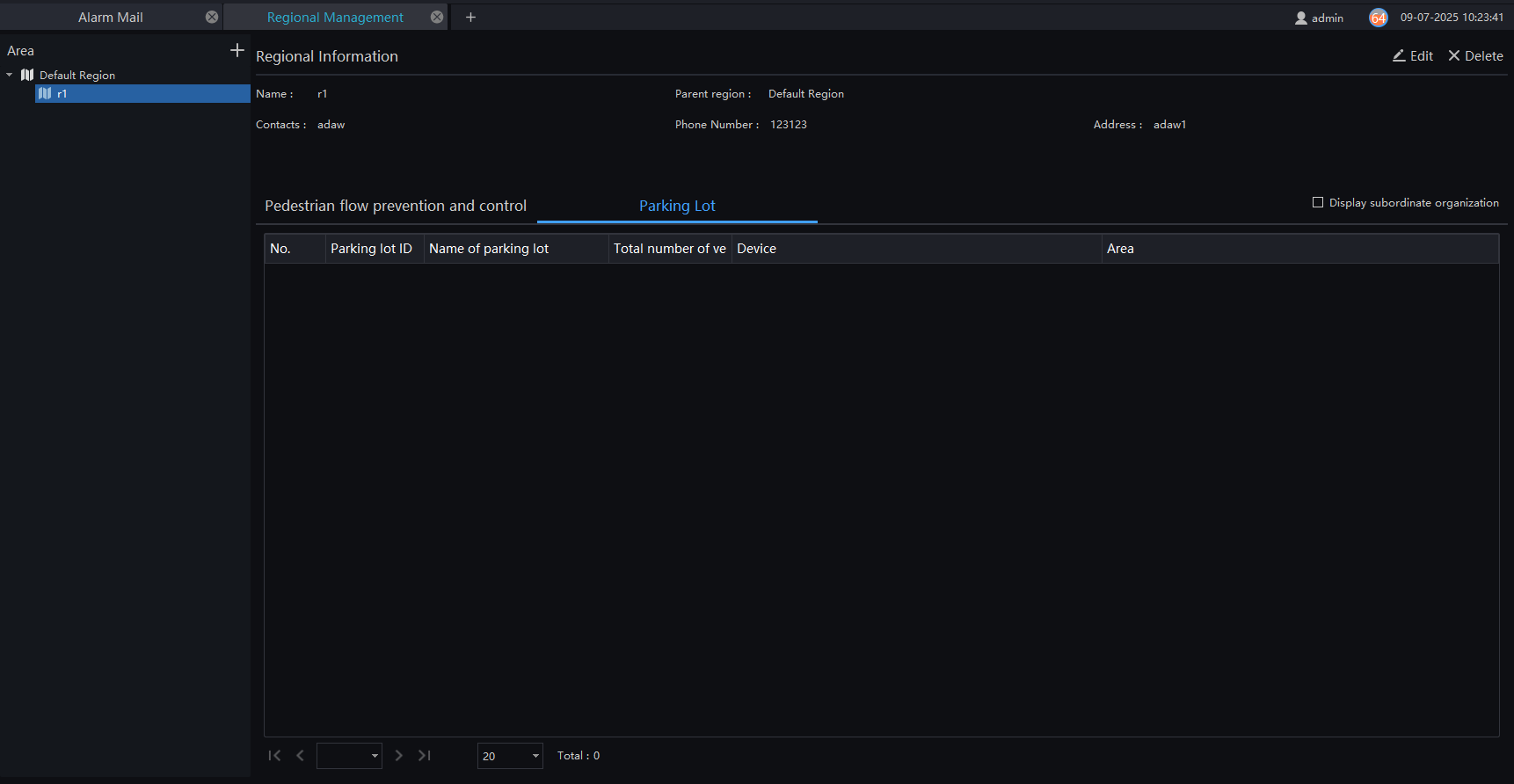
Procedure:
Step 1: Click on  to add an area. Enter the name, region, phone number, contacts, and address.
Step 2: Click on "Save" to save the settings and add multiple parking areas.
Click on "Save and New" to save the current settings and add another one, as shown in Figure 6-27.

-
Click on "Edit" or "Delete" to manage regional information.
-
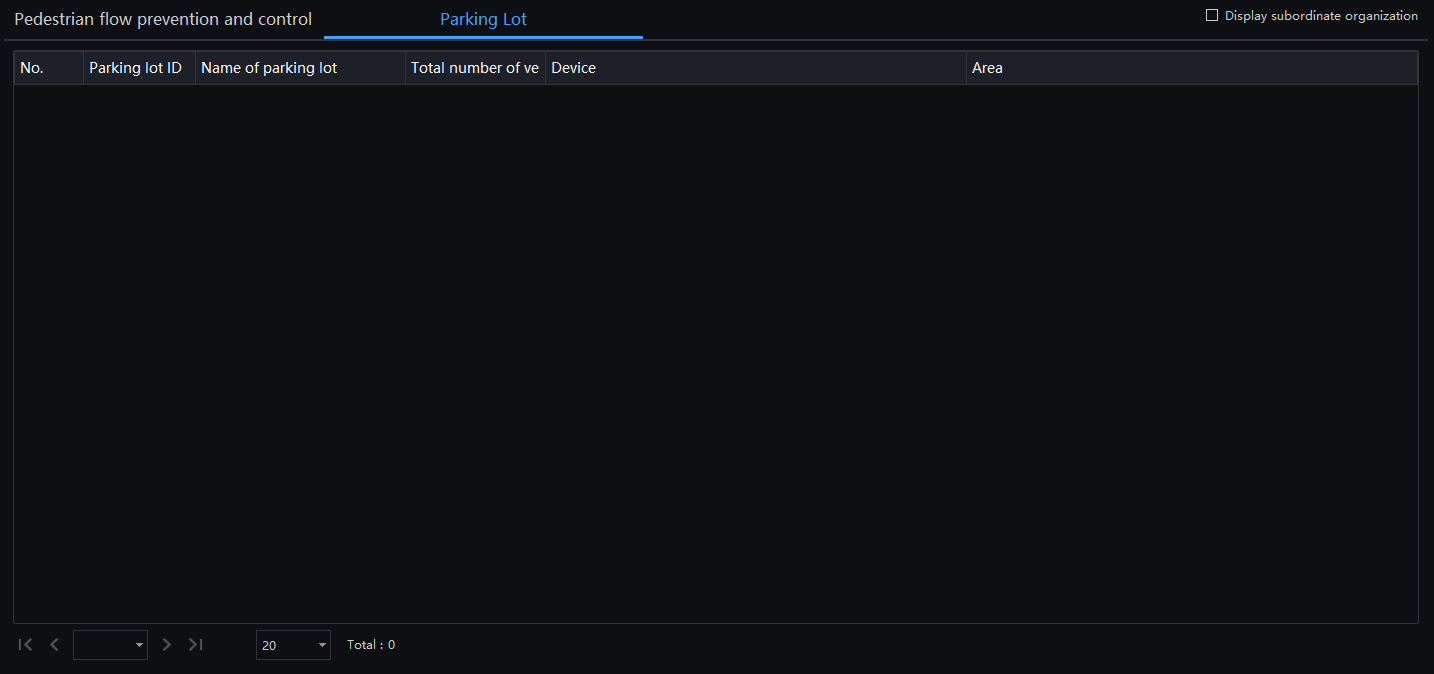
Select the parking interface to view parking information, including:
- Parking ID,
- Name,
- Total number of vehicles,
- Device,
- Area,
- Subordinate organization.
This is illustrated in Figure 6-28.
The areas configured in the Regional Management interface apply to both Parking and Parking and Pedestrian flow prevention and control. If the user wishes to modify Parking and Pedestrian flow prevention and control regions, they must access the Regional Management interface to make the changes.
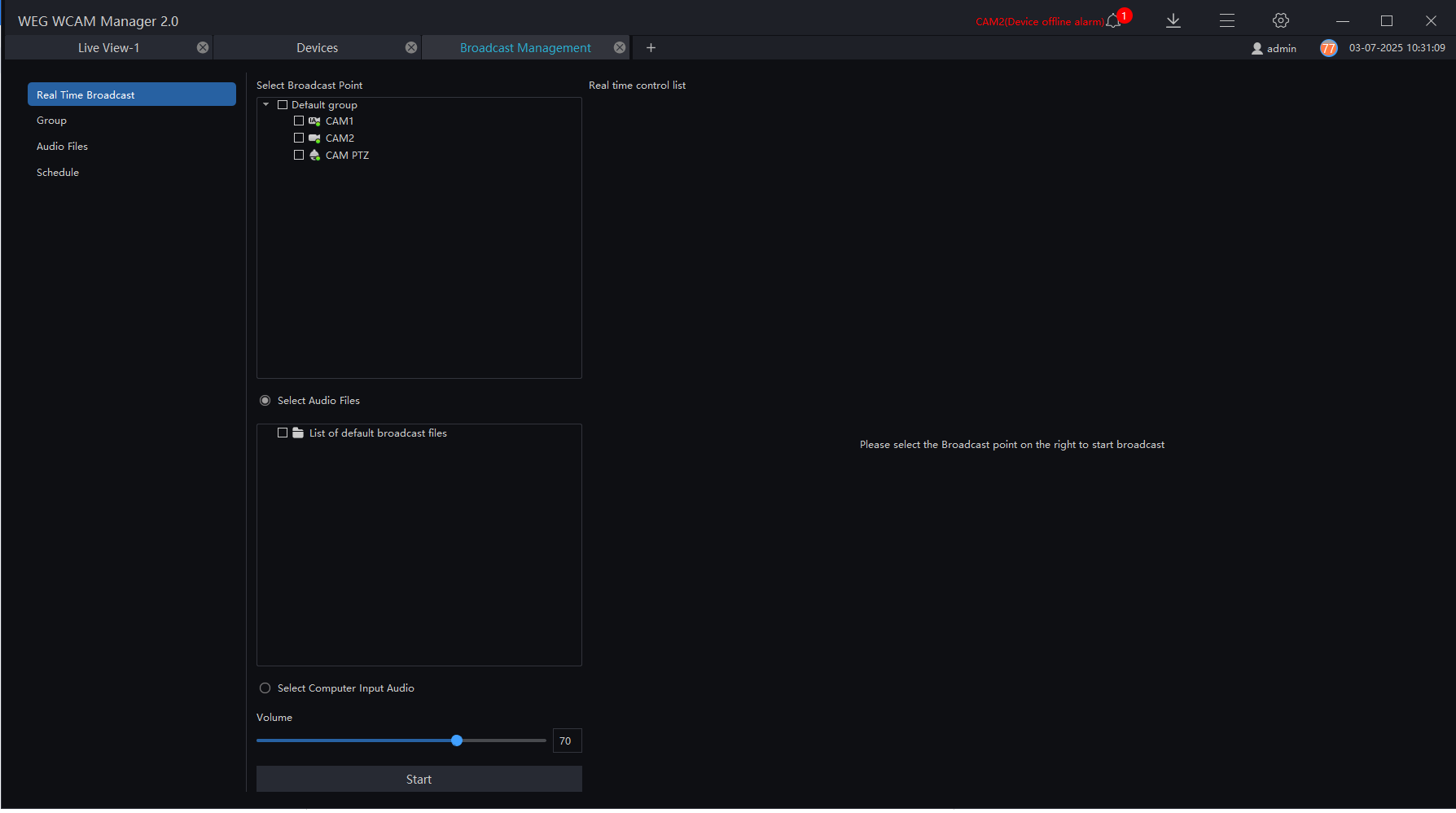
6.9 Broadcast Management
For cameras with a speaker or connected to an audio output device, they can play radio broadcasts. The computer where the platform is installed must be connected to a microphone for audio collection. Click on "Broadcast Management" to enter the settings page. Choose the channel to play, click on "Start," and the selected camera will play the platform's audio. Click on "Stop" to turn off the playback.