5. BASIC FUNCTIONS
5.1 Live View
In the Live View interface, the following actions can be performed:
- Watch real-time video;
- Execute a real-time video tour;
- View local videos;
- Capture images (screenshots);
- Enable or disable audio;
- Start the voice intercom;
- Zoom in on the video;
- Change the video stream;
- Save custom layouts;
- Use the 3D Positioning feature;
- Control the PTZ (Pan-Tilt-Zoom) function.
Additionally, right-clicking the live video displays a context menu, allowing quick configuration of video parameters.
To access the detailed page, simply click Live View in the main menu. The full interface can be viewed as shown in Figure 5-1.
Supports opening up to 4 Live View windows simultaneously and allows the use of a mouse to drag them, making it convenient for synchronized display across multiple screens.
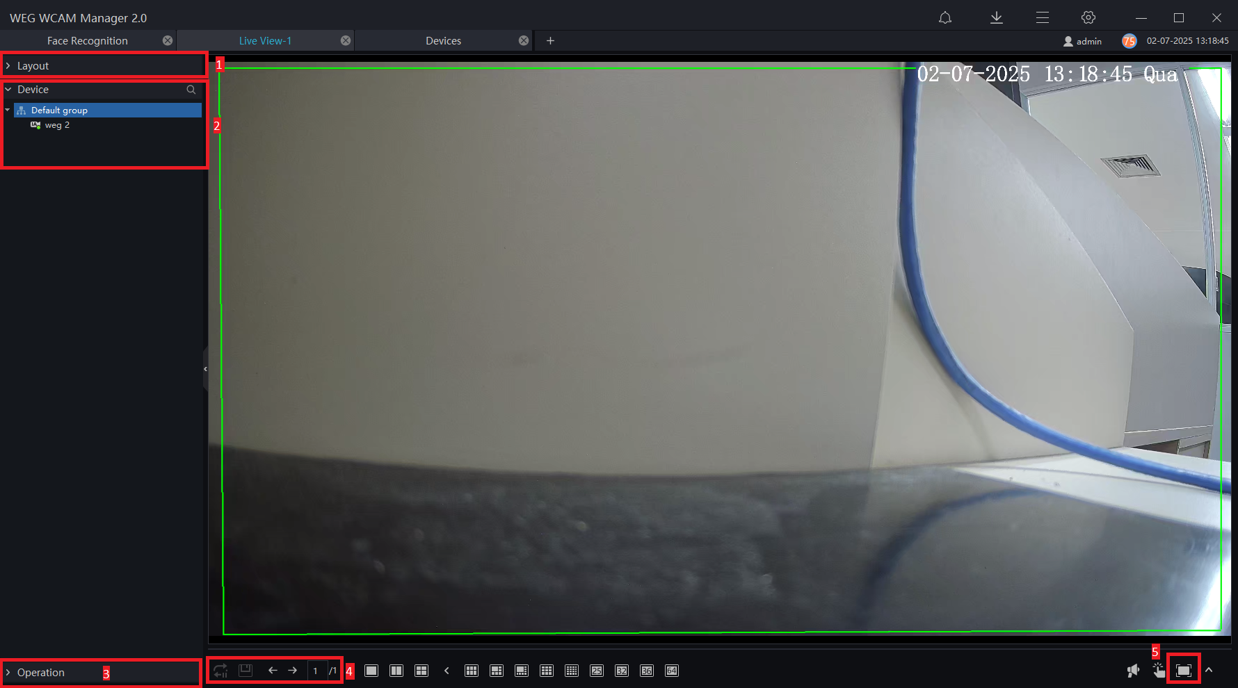
Functions and Descriptions
| Number | Function | Description |
|---|---|---|
| 1 | Layout | Video display format, adds the layout. |
| 2 | Device List | Shows the device list. In the blank space, right-click to choose online-only or show all. Select the device, right-click, and from the menu, you can rename the device, configure it, change the video stream, and view recordings, as shown in Figure 5-2. |
| 3 | Operation | Controls a PTZ camera/Image parameters. |
| 4 | Video Display Layout | Start the tour, save the current layout, single screen, four screens, maximum support for 64 screens. |
| 5 | Full Screen | Displays the live video in full screen. Right-click and click “Full Screen” to exit. |

5.1.1 Layout
In the layout function interface, previously saved layouts are displayed, in addition to being able to select a default layout, as shown in Figure 5-3.

5.1.2 Device
Displays the list of devices associated with the current user account, as shown in Figure 5-4. Users can watch real-time videos by double-clicking or dragging and dropping the mouse onto the desired channel.

5.1.3 Operation
This function is only available for PTZ cameras and supports direction control, positioning operation, and tour operation.
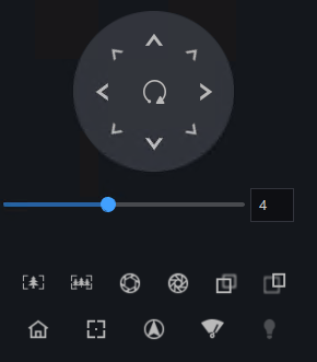
PTZ Operation: Adjusts the full-scale movement of the PTZ, lens zoom, editing and control, zoom in, zoom out, iris opening and closing, near focus, distant focus, focus, start, orientation, wiper, and turning on the light. Shown in Figure 5-5.
Preset: Sets the name and current position as a preset position to facilitate tour operation, as shown in Figure 5-6.
Tour: You can configure the tour to allow the camera to rotate repeatedly based on the tours. Each tour includes presets, and the waiting time must be defined, as shown in Figure 5-7.


Scan: You can configure a start point and an end point to allow the camera to rotate repeatedly from the start point to the end point. Select the scan to be set, click on + to add the scan, choose the scan number, set the name and dwell time, as shown in Figure 5-8.

Track: You can record a track to allow the camera to rotate repeatedly based on the predefined track, as shown in Figure 5-9. Select the track to be set, click on + to add the track, choose the track number and set the name, adjust the camera lens, click on “Start Recording” to begin the configuration, adjust the camera lens, and click on “Finish Recording” to complete the track.

Idle: You can enable the idle feature to allow the camera to automatically execute the preset, track, scan, and tour after the waiting time (1 minute ~ 240 minutes). Select the “idle” option, activate the “idle” option, choose the type, name, and waiting time, as shown in Figure 5-10. Click on “Save” to save the settings.

Timer: You can set the PTZ timer to allow the camera to trigger the preset, track, scan, and tour automatically at the defined time. The camera will restore the operation and position after completion. Click on “Set Timer” to go to the timer page, set the start time and end time, as shown in Figure 5-11. Click on “Confirm” to save the settings.
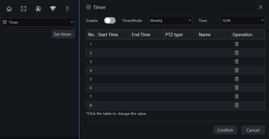
Image Adjustment: Adjust the brightness, sharpness, saturation, and contrast of the image. The default values are 50. The focus can be changed by dragging the right side of the slider or clicking on the left and right axes to change the value. The range is from 0 to 100.


Devices have different functions, and the user can operate the corresponding function in practice.
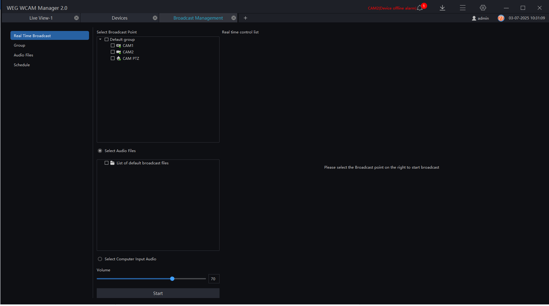
For cameras with a speaker or connected to an audio output device, they can play radio broadcasts. The computer where the platform is installed must be connected to a microphone for audio collection. Click on "Broadcast Management" to enter the settings page. Choose the channel to play, click on "Start," and the selected camera will play the platform's audio. Click on "Stop" to turn off the playback.
5.2 Playback
5.2.1 Playback
In the "Playback" interface, the front-end device video can be played and downloaded, in addition to supporting synchronous playback of multiple channels and playback control operations. On the main menu page, click on "Playback" to enter the detailed page, as shown in Figure 5-15.
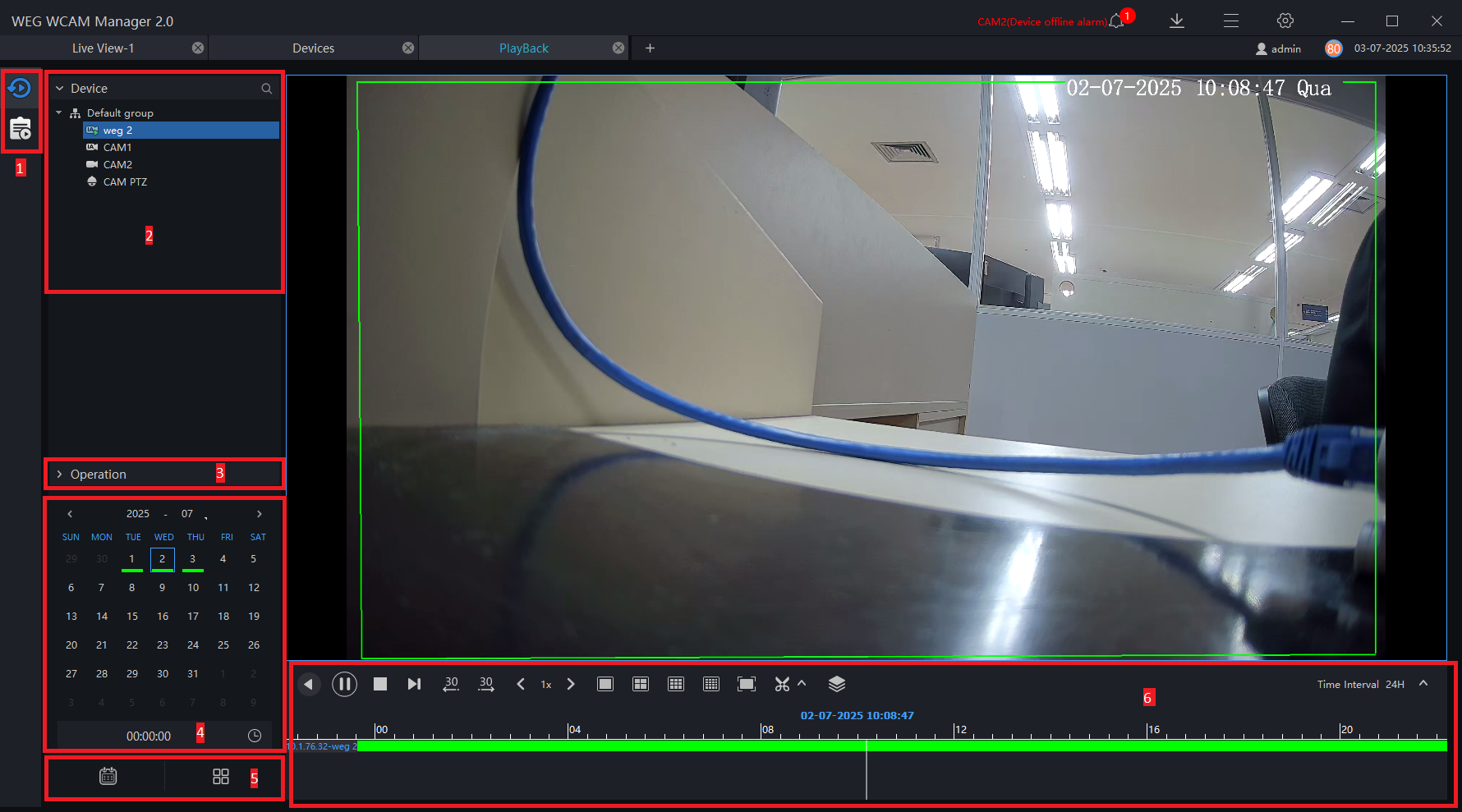
| Number | Function | Description |
|---|---|---|
| 1 | Playback/Event Playback | Select playback or event playback (when devices with SD cards are connected to the platform, the user can view event playback) |
| 2 | Device | Displays the devices configured on the platform |
| 3 | Operation | - Configure and control PTZ cameras - Configure image parameters |
| 4 | Calendar | Displays dates, with a green bar below the date indicating that there is a recording Time can be manually entered on the clock |
| 5 | Show or Hide Calendar/Grid | Open or close the calendar/video grid |
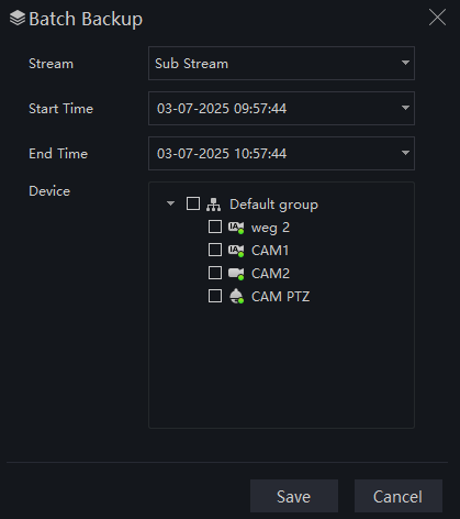
| 6 | Operation Bar | Video operations: operation, timeline, display , Rewind , Rewind , Pause / Play , Pause / Play , Stop , Stop , Next frame , Next frame , 30s backward/30s forward , 30s backward/30s forward , Change playback speed , Change playback speed , Display Layout , Display Layout , Full Screen , Full Screen , Download video from backup device , Download video from backup device , Perform batch backup of multiple videos or recording files , Perform batch backup of multiple videos or recording files , Select the progress bar format , Select the progress bar format |
5.2.3 Play the Device's Video
Procedure
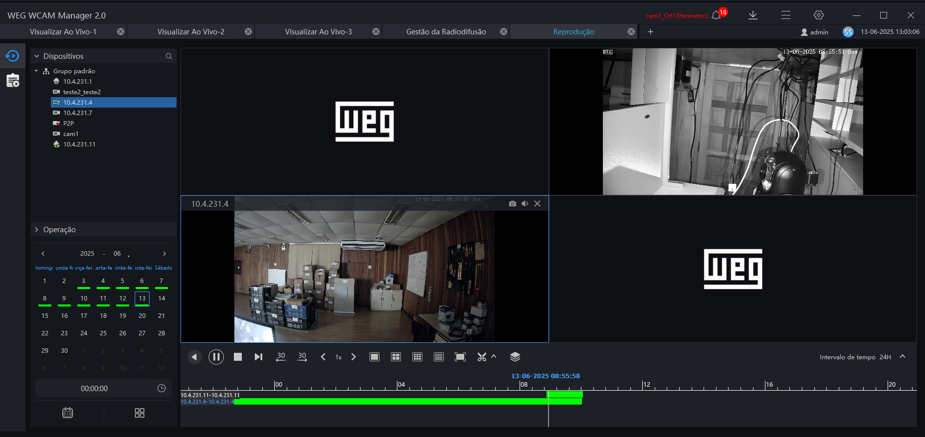
Step 1: Select the display layout mode (supports synchronous playback of multiple devices).
Step 2: Select the device from the device list to play the recording.The video will automatically start from the current time.
Step 3: Select the desired interval as shown in the image below:

Step 4: Select the operation tool in the toolbar to watch the video playback according to your needs.
5.2.4 Backup the Device's Video
Procedure
Step 1: Click on  , the video will start playing, and the icon
  will be displayed. Drag the timeline to quickly copy the video and download it in MP4 format.
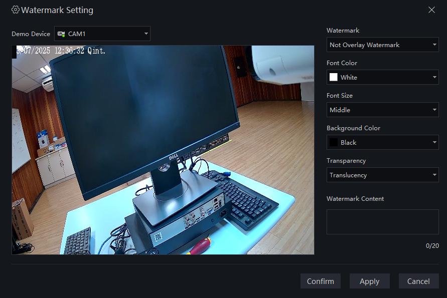
Step 2: Click the checkmark to complete the selection and copying of the video. A download interface will then be displayed, as shown in Figure 5-19.
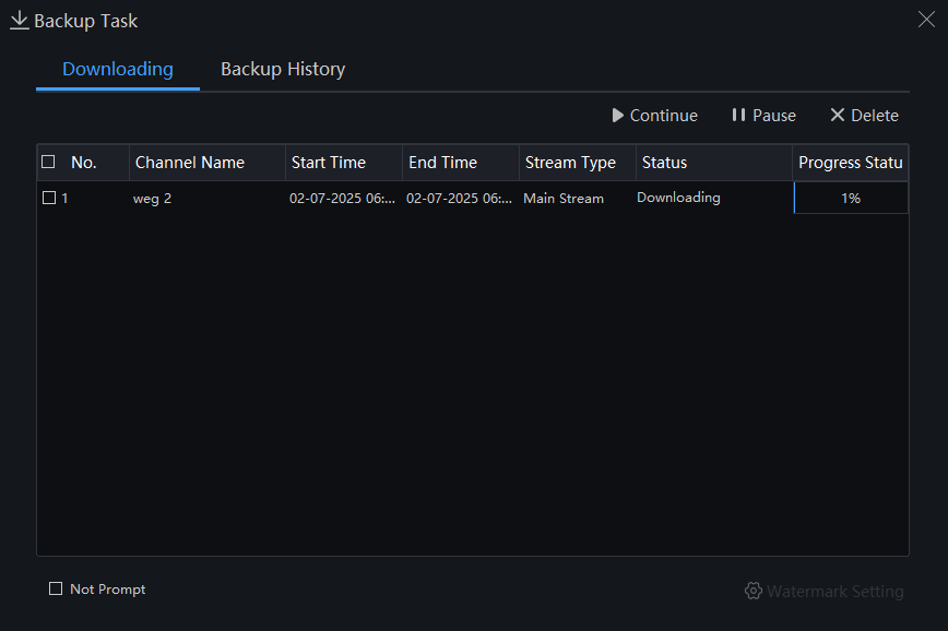
Users can set the watermark for the download recording. Click on "Watermark Settings" to access the configuration page. Watermark (Overlay Watermark or Not Overlay Watermark), set the font color, set the transparency, enter the watermark content, click "Confirm" to save, and click "Apply" to apply all settings to the download recording.
Users can click the download icon at the top of the interface.

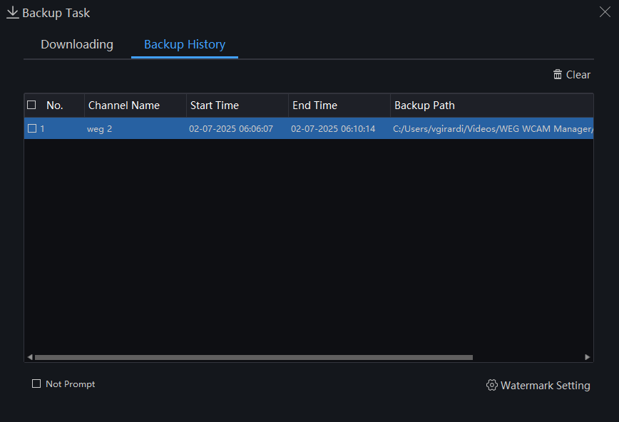
Step 3: Click on "Backup" in the top right corner of the interface to view the start and end time of the downloaded video and the path where it was saved.
5.3 Real-time Alarm
In the Real-time Alarm interface, real-time device alarm information can be received and processed individually or in batches.
In the main menu, click on "Real-time Alarm" to enter the detailed interface, as shown in Figure 5-22.
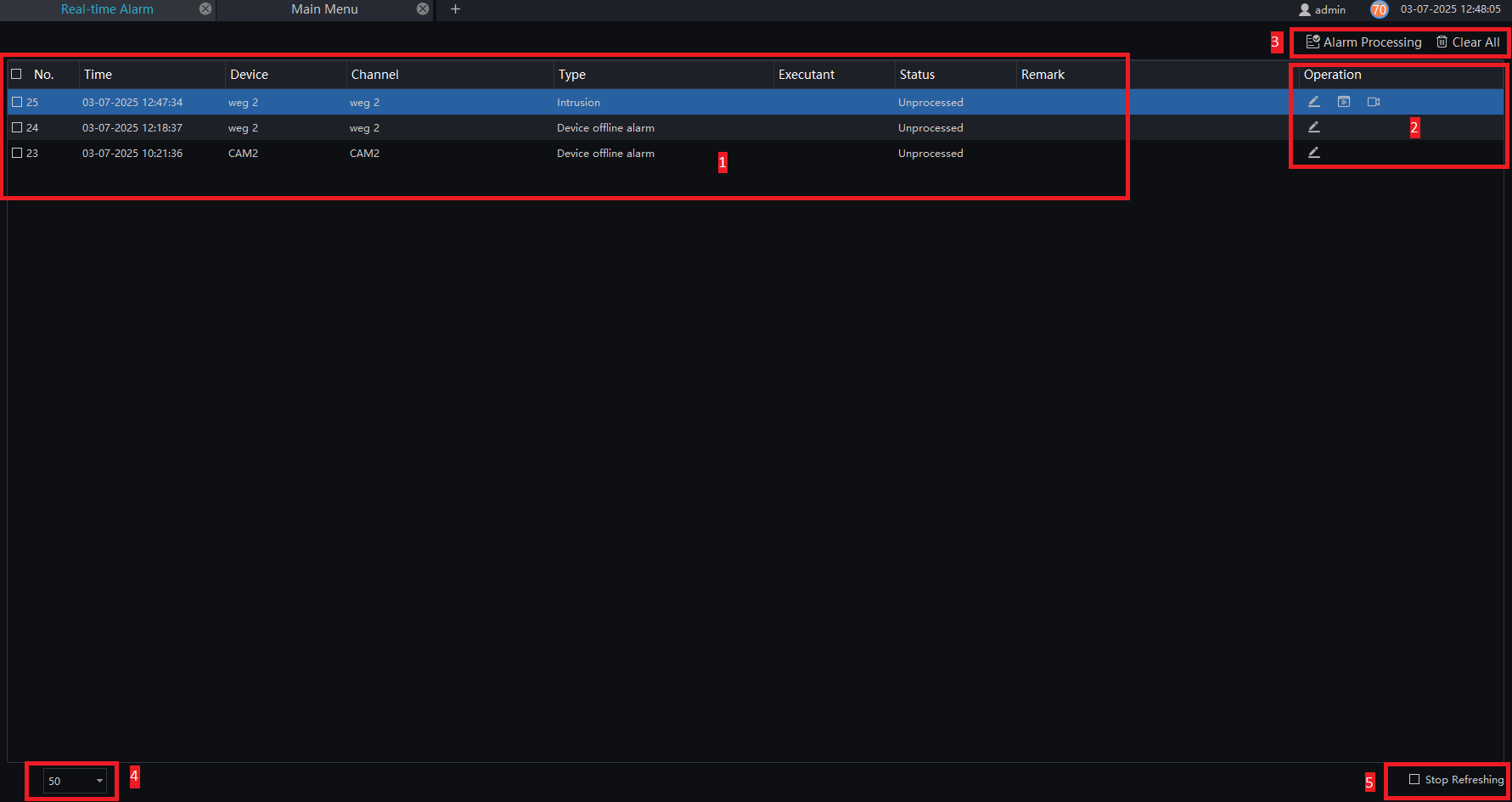
| Number | Function | Description |
|---|---|---|
| 1 | Alarm Display Area | Displays alarm-related information |
| 2 | Alarm Operation | Alarm processing, alarm playback video, live video |
| 3 | Alarm Processing | Processes specified alarm information, click "clear" and the current alarm will be cleared. The thermal camera alarm can be exported, and the information includes comments, summary, action, temperature, alarm time, and so on. |
| 4 | Display Count | Number of alarms on the current page |
| 5 | Stop Refreshing | Check to stop updating the real-time alarm |
Procedure:
Step 1: You can quickly access alarms by clicking the icon  in the upper right corner of the screen.
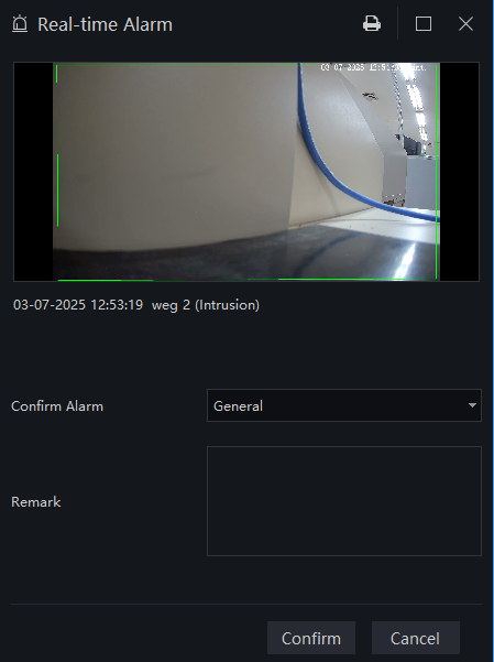
Step 2: Select the desired alarm, click the icon  , and a pop-up window will appear. In this window, you can describe and classify the alarm.
Step 3: Click on  to play the alarm occurrence video for 30 seconds.
Step 4: Click on  to view the live video of the alarm device.
5.4 Alarm Search
In the Alarm Search interface, you can access alarm history, view the alarm type, processing status, and device name. Additionally, results can be processed individually or in batches.
In the main menu, click "Alarm Search" to enter the detailed interface, as shown in Figure 5-24.
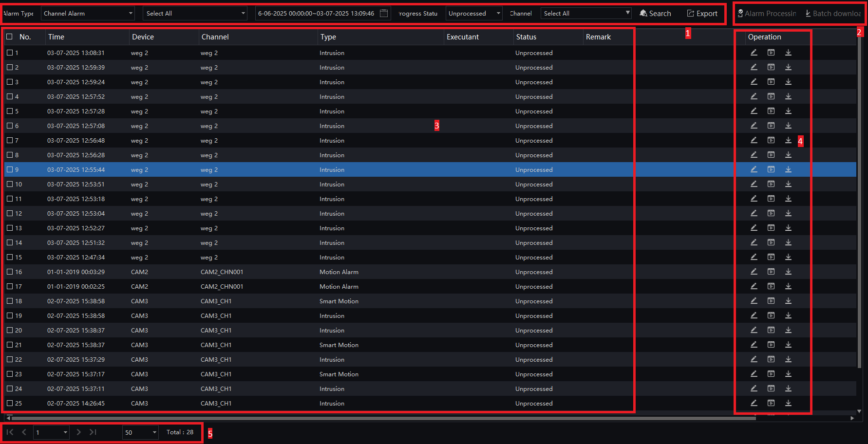
| Number | Function | Description |
|---|---|---|
| 1 | Search Conditions | The user sets the search conditions, chooses the alarm type, progress status, and defines the search time |
| 2 | Process/Batch Download | Click to back up or process the alarm |
| 3 | Search Results | Search results |
| 4 | Operation | Edit, play, process, and Task Backup |
| 5 | Display Interface | Displays the current alarm page, total alarms, and option to switch to the next page |
The processing status of the temperature alarm will affect the alarm statistics. Only the manual processing of alarm information related to overheating statistics can be accurate.
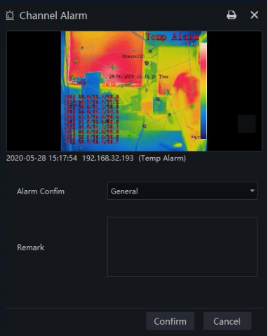

Click on  to export thermal image alarm information, which includes basic camera information, capture, temperature parameters, added comments, summary, action, and so on.
5.5 Layout
In the layout interface, it is possible to link the channel to the window and set the search interval. The layout will be displayed in the "Live View" interface, making video monitoring more practical.
In the main menu, click "Layout" to enter the detailed interface and click on  to add a new layout, as shown in Figure 5-27.
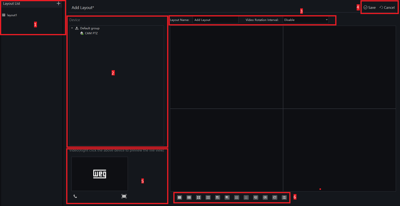
| Number | Function | Description |
|---|---|---|
| 1 | Create new layout | Click on  to create a new layout to create a new layout |
| 2 | Device List | Drag the device to the layout screen |
| 3 | Basic layout information | Set the name of the new layout and define the Rotation Interval |
| 4 | Operation | Save or Cancel the layout configuration |
| 5 | Play the video | Right-click a device to play the video.  |
| 6 | Display mode | Choose the video display mode |
Procedure
Step 1: Click on  in the layout list to create a new layout.
Step 2: Enter the layout name and select the layout arrangement.
Step 3: Define the Video Rotation Interval.
Step 4: Select and hold the mouse to set the channel to be displayed in the layout window. You can link multiple channels in the same window and enable the display interval for users to view multiple cameras.
Step 5: Click "Save" to save the settings.
5.6 E-Map
In the E-Map interface, you can set up a map to facilitate monitoring and locating places. Multi-level submaps are supported.
Supported Files: JPG, PNG, and BMP.
On the new functions page, click "E-Map" to enter the detailed interface, as shown in Figure 5-28.
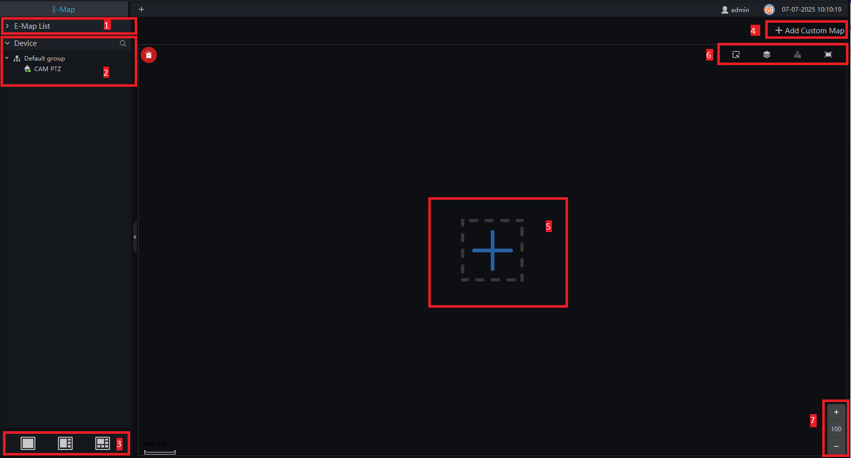
| Number | Function | Description |
|---|---|---|
| 1 | E-Map List | All configured maps |
| 2 | Device | Device list |
| 3 | Display Layout | Map and video display layout |
| 4 | Add a map | Add a custom map |
| 5 | Add a map | Add a map |
| 6 | Map Operations | The user can operate devices on the map |
| 7 | Zoom In/Out | Enlarge the map to set monitoring points |
5.6.1 Add a Map
Procedure:
Step 1: Click on  to add a map:

Step 2: Enter the map name and select the map directory. You have two options: use the map already present in WCAM or add a custom map.
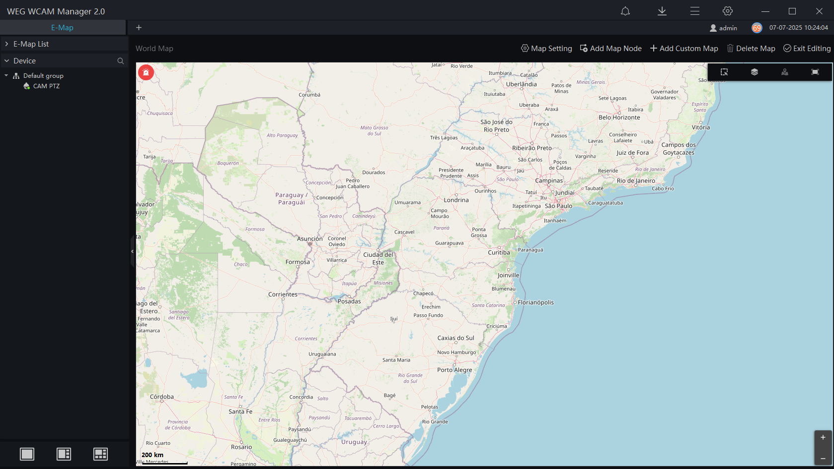
Step 3: Click on "Exit Editing" to save the map.
You can create a submap within the Global Map. Navigate through the map and select the desired area to create a detailed map of that region.
Click on  to create a node map, define a name, and click on "Save" to save the settings.
5.6.2 Edit the Map
Step 1: Click on  to enter the edit status.

Step 2: Click on "Scale," draw a line to act as a scale, and input the actual distance of the line. The scale will be displayed in the bottom left corner of the map page.


Step 3: Click on  to save the edits.
5.6.3 Quick Navigation
Step 1: Click on  .
.
Step 2: Drag the mouse to select the area, and the result will be displayed in a pop-up window, as shown in Figure 5-35.

Step 3: Click on  to filter the devices:
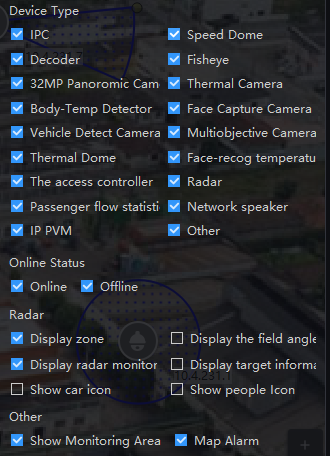
Step 4: If an alarm is triggered, click on  to position the camera, and double-click to view the live video.
Step 5: Click on  to view the alarm information.
Step 6: Click on  to set the screen division.
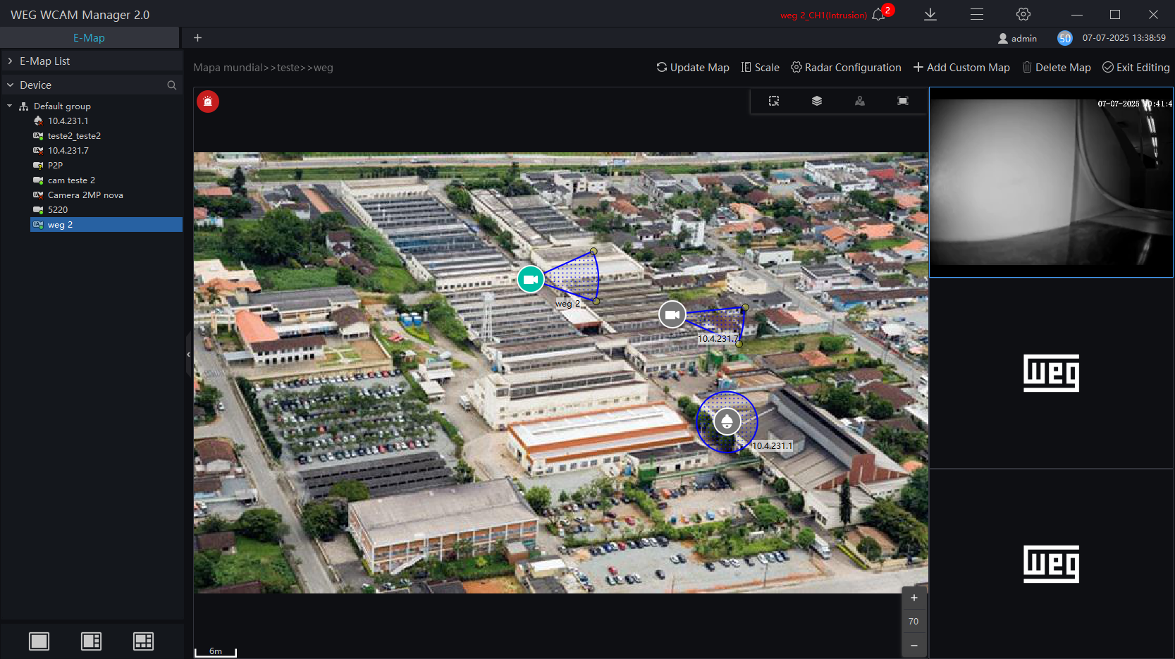
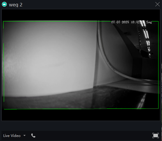
Step 7: Double-click the camera on the map to view the live video or playback, as shown in Figure 5-37.
5.7 Report Statistics
In the Report Statistics interface, users can view alarm statistics for groups and devices. The online device rate is also reported.
On the main menu page, click "Report Statistics" to access the detailed page, as shown in Figure 5-38.
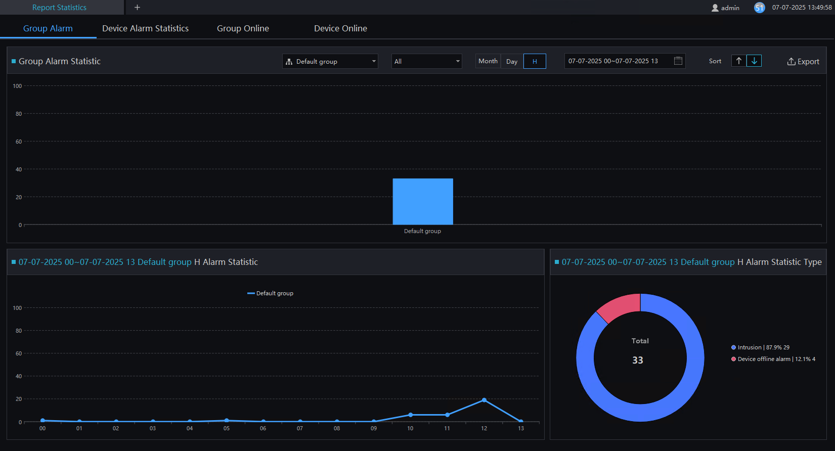
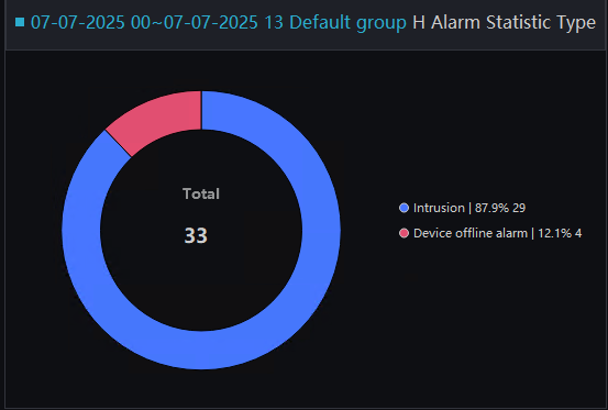
There are three visual display methods for data statistics: histograms, line charts, and pie charts.
5.8 Monitoring Center
The Monitoring Center provides a comprehensive visual management platform. From the map, you can directly view the online status and access other functionalities such as:
- Regional Statistics
- Snapshot Statistics
- 7 Day Statistics
- 24-Hour Traffic Statistics
- Attendance
- Face Snapshot
- Real-time Alarm
- Maps
- Live Alarm Video
On the main menu, click on "Monitoring Center" to access the detailed page, as shown in Figure 5-40.
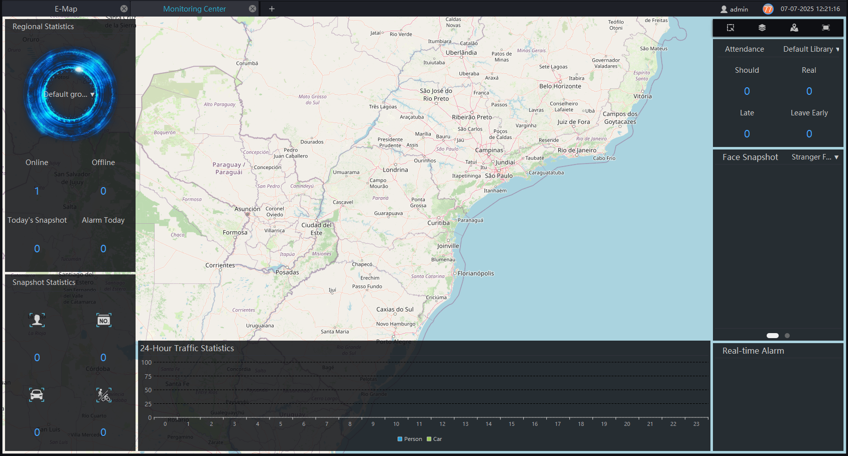
Features Overview:
-
Regional Statistics: Counts the number of online and offline devices in different groups.
-
Snapshot Statistics: Provides statistics on faces, license plates, vehicles, people, and snapshots under the organization.
-
7-Day Statistics: Shows pedestrian traffic, vehicle traffic, and alarm conditions from the past 7 days. This statistic updates daily and cannot be updated in real-time. By default, it alternates automatically between pedestrian and alarm statistics.
-
24 Hour Traffic Statistics: Displays the number of people and cars in a 24-hour period.
-
Attendance: Provides attendance statistics at control points within the group structure.
-
Face Capture: Counts the frequency of strangers and captures individuals with elevated temperatures. By default, it alternates automatically between these two types of statistics, updated in real-time.
-
Real-Time Alarm: Displays real-time alarm information. If the device is connected to the map, you can click to watch the real-time video.
-
Live Video: Switches, in real-time, to alarm videos from devices present on the electronic map.
By clicking on the camera on the map, you can view live videos or replay previous recordings.
5.9 Event Linkage
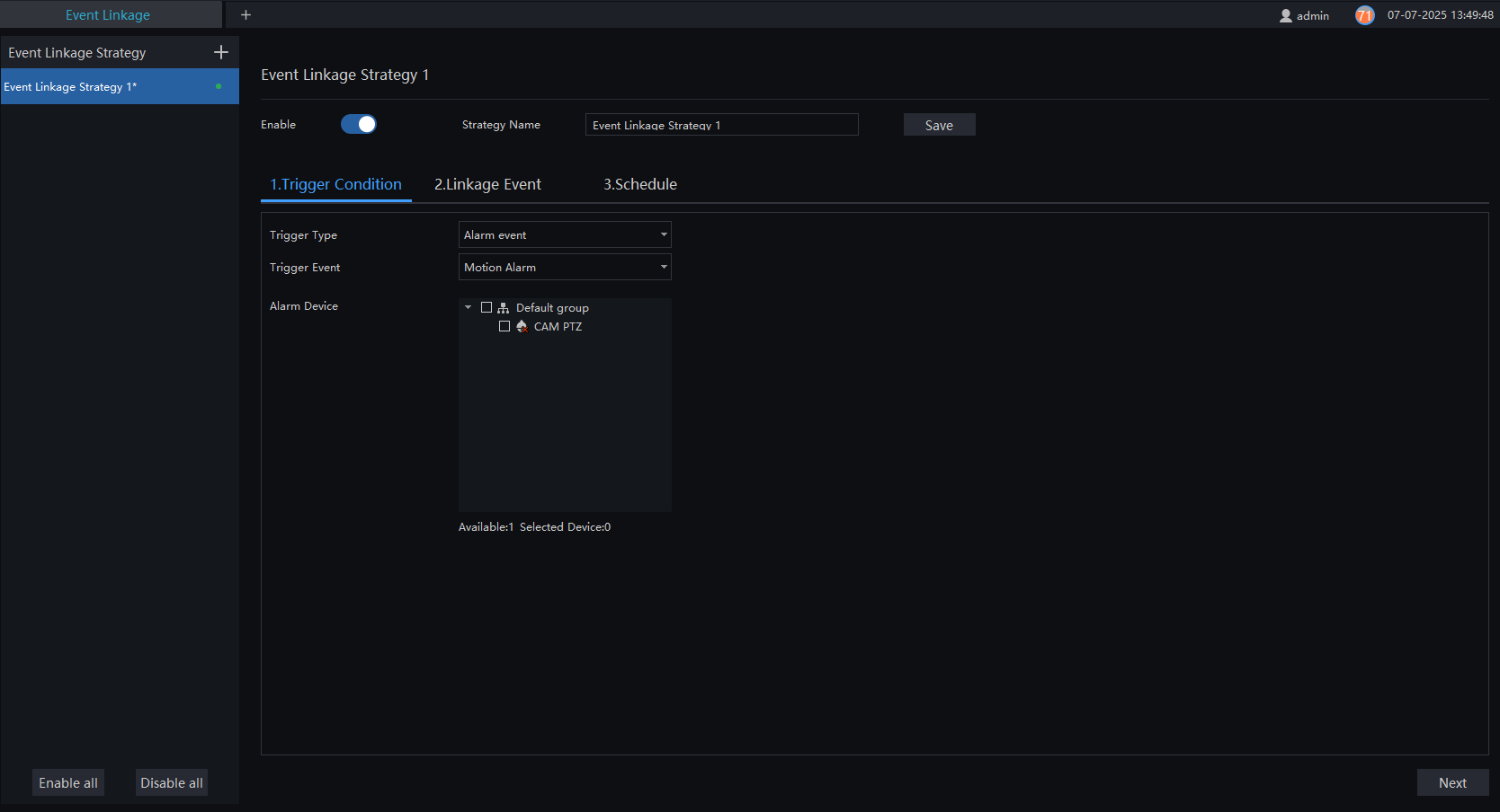
In the Event Linkage interface, users can configure actions related to alarms, including:
- Trigger Condition: Sets the criteria that activate the event.
- Linkage Event: Determines the actions to be executed, such as:
- Sending emails.
- PTZ (Pan/Tilt/Zoom) control.
- IO (Input/Output) output.
- Image capture.
- Voice broadcasting.
- Schedule: Establishes the active period during which the defense will be applied.
Figure 5-41 illustrates this interface in detail.
Procedure:
Step 1: Click on  to add a new event linkage.
Step 2: Enable the strategy and define a name.
Step 3: Choose the trigger condition, as shown in Figure 5-42.

Step 4: If "Timing" is selected, the user needs to define the trigger time and the days to repeat.
Step 5: If "Alarm Event" is selected, the user needs to choose the type of alarm and the desired devices, as shown in Figure 5-43.
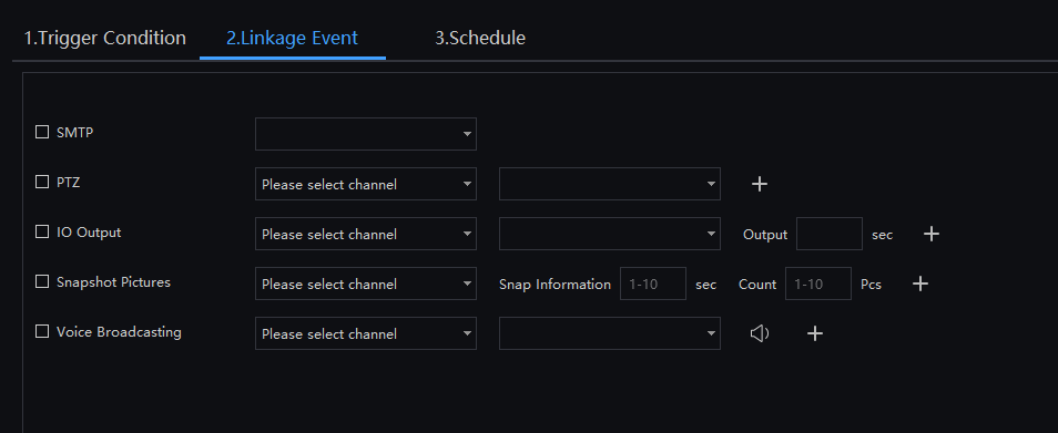
Step 6: Click on the "Next Step" button to define the event linkage. Choose one or more alarm actions, as shown in Figure 5-43.
Step 7: Click on the "Next Step" button to define the defense schedule.
Step 8: Click on "Apply" to save the configuration.
5.10 Snapshot Retrieval
The Snapshot Retrieval interface is used to locate images captured and linked to events. During the defense setup, you can search for the alarm source equipment and review panoramic images captured by other linked equipment.
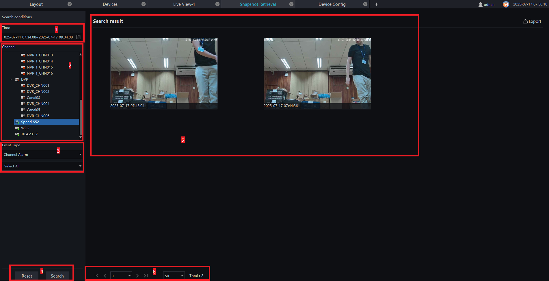
Key Features and Functions:
| Number | Function | Description |
|---|---|---|
| 1 | Time | Click on  to open the calendar and set the search range. The maximum search range is 7 days. to open the calendar and set the search range. The maximum search range is 7 days. |
| 2 | Channel | Select the alarm source device. |
| 3 | Event Type | Choose the event type and alarm type. |
| 4 | Reset/Search | - Click on "Reset" to reset the search conditions. - Click on "Search" to perform the search. |
| 5 | Result | Displays the search results. Click on an image to view detailed information. Results can be exported to a local folder. |
| 6 | Page | Displays device pages, the next page, and the number of snapshots. |